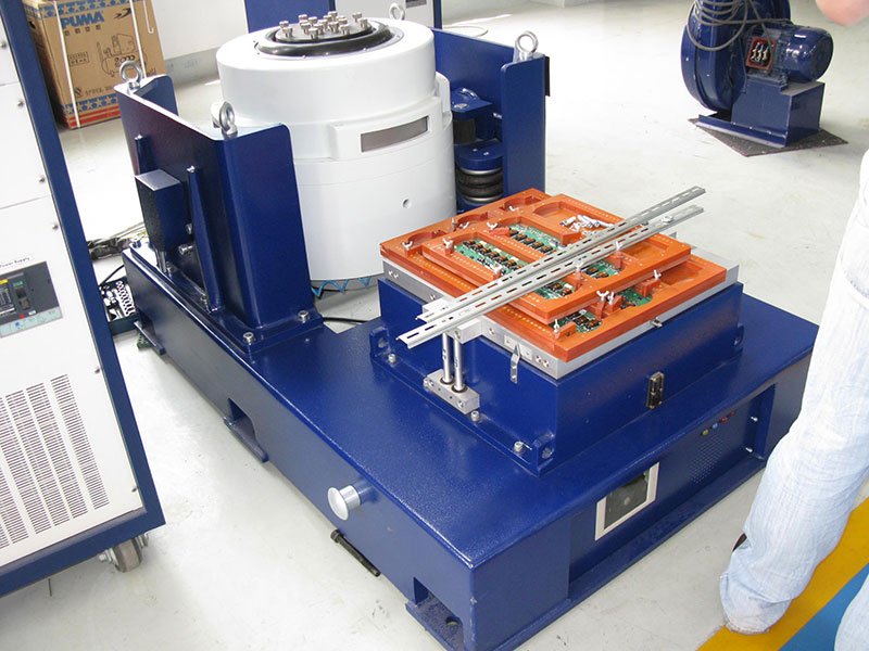
The most common vibration test for electronic element is pcb vibration testing, because electronic components are subjected to transient or permanent dynamic mechanical stress during use, which can compromise their performance (for example, mechanically induced cracking in PCB systems or wear corrosion in connectors and other components). Therefore, electronic element vibration testing is particularly important in applications where electronic devices or systems are exposed to vibration, such as in automotive, aerospace, industrial and consumer electronics.
In this paper, HI-ReL EEE components of electronic components in aerospace spacecraft are taken as an example to carry out some simple test flow.
Electrical equipment in rocket boosters and spacecraft must be able to withstand high dynamic loads and various mechanical shocks. During space launches, these devices will face a variety of challenges, including motor excitation during liftoff, jitter, and low-frequency vibration during shutdown. In addition, during space travel, these devices will also be subjected to large shock loads, especially during the rocket separation phase, which involves high-frequency shock waves.
These dynamic loads are the main cause of different failure modes in electronic component (EEE) systems. For example, excessive deformation and acceleration (loads in g) subjected to assembly system components can cause serious damage to connectors, surface mount devices (SMDS), printed circuit boards (PCBS), and other electrical components.
A clear example of vibration-induced failure in SMD systems is the dimming of pads in BGA, CGA, and bottom end elements. Being able to simulate this mechanical stress on the ground or study the dynamic properties of structures is therefore critical to successfully validate new EEE components suitable for space applications.

For a comprehensive vibration study, the following diagram shows the different stages of a typical vibration test under ECSS-Q-ST70-08C, which is followed by a European Space Agency (ESA) project.
These tests are divided into two parts corresponding to high level vibration: sinusoidal sweep vibration and random vibration. These vibrations must be applied independently on the three orthogonal axes. According to the test procedure, before and after each high level vibration (whether sinusoidal or random), a low level sinusoidal vibration measurement is performed to analyze the mechanical properties of the device under test (DUT).

In the first method of determining the mechanical weakness of the device under test (DUT), the system receives a sinusoidal stimulus of increasing frequency, as shown in Figure 3. Typically, logarithmic sweep rates are used to compensate for the longer time it takes to complete a cycle at lower frequencies.

Prior to the advanced vibration test, a low-level sinusoidal vibration measurement is performed. This precaution is taken to analyze the mechanical impedance of the test fixture /DUT assembly over the inspection frequency range. This low-level pretest allows us to evaluate the natural frequency of the system in a safe manner to avoid excessive damage due to nonlinear responses. For example, a printed circuit board may exhibit a strong resonant response over the test frequency range. At this resonant frequency, the installed equipment and solder joints on the PCB will be subjected to extremely high acceleration, far exceeding the acceleration applied by the test system. Our preliminary studies in the lab, using simulation models (advanced pretests) and real systems (low pretests), were designed to avoid this adverse effect. In addition, using sinusoidal vibrations to determine resonance conditions on a PCB or other system is an effective way to understand how mechanical vibrations propagate through a device, and can help designers improve designs by strengthening or weakening elements and reducing the risk of fatigue failure.
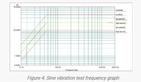
A high-level sinusoidal scan is similar to a low-level sine wave measurement, during which the system is subjected to uniaxial sinusoidal motion with increased frequency. In addition, the acceleration (∝ displacement x frequency 2) is modified according to the test profile used. For example, Figure 4 shows a frequency domain plot of the test (acceleration vs. frequency), where acceleration increases linearly with frequency until it reaches a given constant value. This test is used to assess the effects of periodic and semi-periodic heavy loads on DUT.

In practical applications, sinusoidal vibration rarely occurs because it does not represent the real situation experienced by the device under test. For example, the dynamic stress generated in a real scene is usually not periodic or predictable, unlike a sinusoidal waveform. In fact, the vibration environment faced by most installation electronic equipment is the use of random vibration conditions.
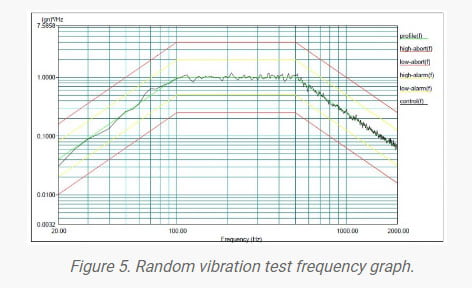
To simulate a more realistic dynamic stress, random vibration tests excite all frequencies in a given range at the same time. The stimulus is applied in a semi-random manner, with its spectrum constantly changing in amplitude and phase. Still, the process is not completely random, as the average adjusts to a given test curve, as shown in Figure 5. In this way, vibration levels are kept within prescribed limits to ensure that the tests reproduce the operating conditions of the equipment under test and that the tests are carried out under safe conditions. In such tests, the vibration curve is defined in the frequency domain and analyzed in terms of power spectral density (square of acceleration divided by Hertz), units that can provide more meaningful information about the applied dynamic stress. The signal is applied to the device under test for a given period of time to verify the function of the device under such conditions.

All described tests are designed to study the effects of dynamic stress on EEE (Electronic, Electrical, and Electromechanical) components and other systems. Therefore, After completing element vibration testing, the equipment under test must be thoroughly inspected and analyzed to look for possible structural anomalies and/or signs of failure. JOEO offers a variety of in-house services for the final electrical characteristic analysis and physical inspection of test systems.
As a leading electrodynamic shaker manufacturers in China, JOEO provides professional vibration test solutions to customers in various industries. We have extensive experience in vibration testing in the aerospace, electronic equipment manufacturing and automotive industries.
If you would like more detailed information about electronic element vibration testing, such as PCB vibration testing, electrical connectors and other key components of the vibration test technology, you can contact our experts now!
